
Backlash and its importance in the pitch system of a wind turbine
By Cory Mittleider on 7/1/2026
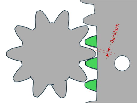
Fig 1. Gap between drive pinion tooth and driven tooth is called backlash
We all know that nothing is perfect, even when using highly precise CNC and the latest machining techniques, manufactured components such as bearings will have some very small deviation throughout a production run. If not considered in the design these deviations can impact component, or even system, performance.
Additionally, each manufacturing process will have its own tolerances that can affect the rest of the part. These effects can add together to either exaggerate or negate individual deviations. This is called tolerance stack, which is why completed assembly will have finished part tolerances allowing the manufacturer to adapt their process controls on individual subcomponents to deliver a final assembled part meeting the intent of the application designer.
Application designers know this and will do 2 things to accommodate this.
First, the designer will review the application to determine an allowable amount of deviation, this is called tolerance. These tolerances are what the manufacturers use in their quality checks to qualify good parts or scrap parts that don’t meet them.
Second, the designer will review the potential impact on the overall application, and if there is potential for this tolerance to affect performance, they will implement ways to avoid this such as instructions on how to assemble or operate the equipment to avoid these detrimental effects.
Fig 2: Animation showing how tightest teeth are identified and painted green during production
Blade (Pitch) Bearings – Electric Pitch Machines
Electric pitch systems use an electric motor connected to a “pitch drive”, typically a multi-stage planetary gearbox, to decrease speed and increase torque. On the low-speed side of this gearbox there is a drive pinion that engages with gear teeth that are manufactured as part of the blade bearings inner or outer ring; this is what pitches the blade.
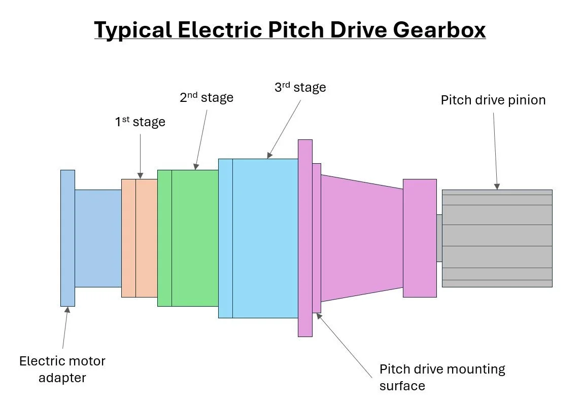
Fig 3: Generic pitch drive diagram showing the different sections of the drive.
Gear Mesh
The contact between the drive pinion and the teeth on the bearing is called the gear mesh. This gear mesh is a critical interface to long term operation of the pitch system. The measurement of this gear mesh is called backlash. This is quantified by measuring the gap between the pinion tooth and the gear tooth on the driven ring.
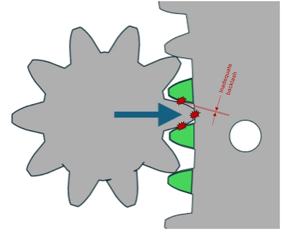
To tight (not enough backlash)
High pitching torque requirement
Accelerated tooth wear
Premature failure of pitch drive gearbox
Fig 4: Image showing too tight of backlash
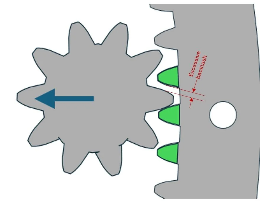
Too loose (too much backlash)
Shock load on pitch system
Accelerated tooth wear
Fig 5: Image showing too loose of backlash
Coming together
Now that we know the importance of gear mesh we should consider what effect the manufacturing tolerances of the bearing, hub, and other components in the pitch system can affect this gear mesh. The good news is that this phenomenon is well understood by manufacturers and designers so there are already best practices developed to address this. This includes 2 primary facets:
Identification
While going through final quality control and doing the checks required to make sure that critical features are within the tolerances described, the bearing manufacturer will identify the area in the toothed ring that would create the tightest contact with the pinion. This will be marked, typically with green paint.
Deviations that make it smaller will result in a tighter mesh (low backlash) while deviations that make this circle larger will result in a looser mesh (more backlash).
Adjustment
Designers will offer a target backlash measurement for installation.
Designers will include a way to adjust the pitch drive engagement that allows the user to inspect and adjust backlash to achieve this target during installation.
Note: This target is typically .03-.04 x gear modulus, check OEM instructions
Example:
For a common electric pitch turbine wind turbine, the geared teeth will be on the inner ring. In this case the bearing manufacturer will identify and mark 3 teeth in the area that these tolerances provide the smallest circle. The basic outline of installation will look like this:
Install outer ring of bearing on to hub, indexed according to instructions.
Bring green teeth into area they will engage with pitch drive pinion.
Install pitch drive.
Measure backlash with feeler gauge as described in manual.
Adjust pitch drive position to achieve desired installation backlash.
Proceed with following reassembly steps per OEM instructions.
These basic steps are outlined in the following animation.
Fig 6: Animation showing generic installation of bearing to hub and backlash setting steps
Important note:
These green teeth will be in a different position on every bearing. They are for reference in setting backlash only and are not a reference to blade orientation. In fact, they may be completely outside of the typical operating area of the bearing, but they are in fact the desired location to set the backlash for certainty that the system will avoid a too tight scenario described above.
Other markings
In addition to the green teeth described above, these bearings typically have several “S” marks stamped or painted on them. These “S” marks indicate the soft spots of the internal raceway system, and these locations are often reference as part of the installation procedure for both the outer ring to hub and for the blade to inner ring. (see images below) Note: some OEM’s use pins for locating the outer ring relative to hub. In such cases the soft spot will have a certain angle (included in design) with reference to these pins.
Fig 7: Image of “S” mark both stamped and painted on a blade bearing. This indicates the location of the raceway soft spot in the bearing.